How to Windows Kernel debugging between Virtual marchine with Network .
Test Setting
Debugger and Debugee have same settings.
|
Basically, Kernel debugging dodel is a diagram that is following <fig .1>.
<fig .1>
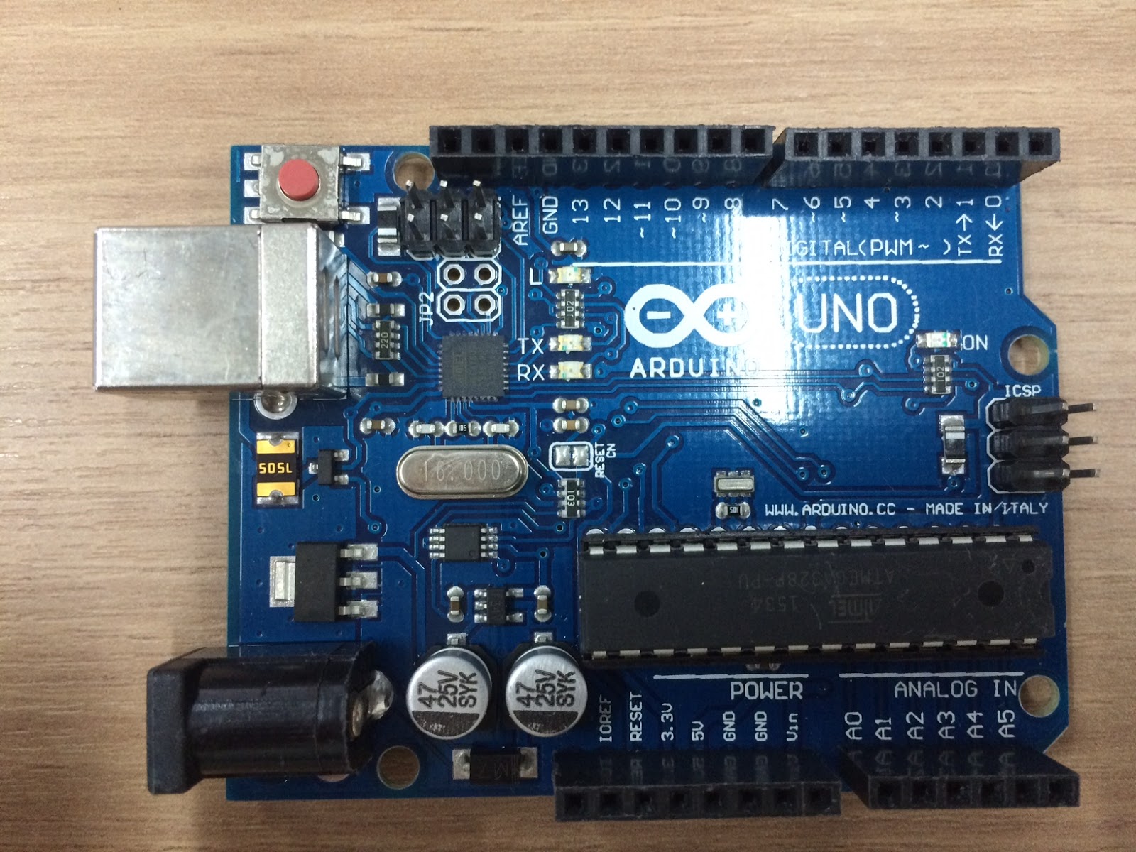
Therefore, It needs 2 PCs or 2 VMs for debugging, and it has to be connected by Network each o other.
And, Network kernel debugging is suppored by WDK 8 and later..
However, Despite of Supprting formally, From the ‘msconfig’ GUI wizard , it does not choose ‘NET’ mode…
ㅜ.,ㅜ….
But, It became more simpler than using a serial port.
hoooray~.
Steps for the Debuggee
- Setting up the debug mode with a network address , then Run commands next..
bcdedit /debug on
bcdedit /dbgsettings net hostip:192.168.2.8 port :50000
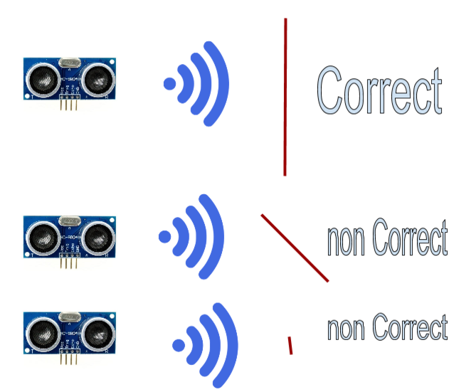
※ A parameter hostip means address of ‘Debugger’ that is connected with ‘Debugee’.
※ A command returns Key and you should to note or rememeber that key.
※ And, you are going to see your debug settings with following command.
(bcdedit /dbgsettings)
|
- and Reboot
Steps for The Debugger
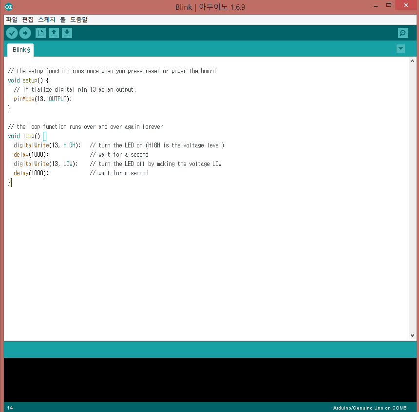
- Start a Windbg.
- Click on the File > ‘Kernel Debug’
- Move on ‘NET’ tab of the popup window.
- Enter value of port and Key you memo. ( ex . sdkjhs8sjhdksjd87sdjhksjdnnjhskd9sdks)
- Click ‘OK’
- It will printed “Waiting connect..” .
If it still connecting… - Reboot debuggee , and click on the Debug > break .
After it is connected, you want to boot debugee continually. - Click on the Debug > go.